The Problem
Two remote security nodes at farm entry points — each housing a camera, directional wireless link, and a PoE switch — are powered by individual solar systems using Victron BlueSolar MPPT 75/15 charge controllers. Knowing whether those solar systems are healthy, and getting early warning of any fault, is directly useful: a dead camera means an unmonitored gate. The BlueSolar 75/15 has no Bluetooth and no built-in network connectivity — VE.Direct is its only data interface.
The off-the-shelf Victron solution — a VE.Direct to USB cable connected to a Raspberry Pi — would require a single-board computer in each weatherproof outdoor enclosure: additional cost, additional power draw, and an additional maintenance surface at a remote location. Each enclosure already contained a PoE switch providing both power and Ethernet to the camera and wireless hardware. A PoE-powered, Ethernet-connected ESP32 board could tap that existing infrastructure directly, eliminating the need for any additional power supply or cabling.
The design problem was electrical: VE.Direct is not directly compatible with a 3.3V microcontroller, and Victron explicitly warns that their MPPT charge controllers have minimal protection on their VE.Direct pins.
The Electrical Problem
VE.Direct is a 4-pin JST-PH 2.0 UART interface running at 19,200 baud — simple to parse, well-documented, and used across Victron’s MPPT, BMV, and inverter product range. The complications are in the electrical details.
Voltage levels
VE.Direct logic levels are not standardised across the Victron range. MPPT charge controllers operate at 5V. The ESP32 is a 3.3V device and is not rated as 5V-tolerant on its GPIO pins. A direct connection is outside Espressif’s absolute maximum ratings, and relying on undocumented tolerance across silicon revisions is not a design margin — it is an assumption.
Galvanic isolation
Victron’s own documentation states the VE.Direct TX and RX pins connect almost directly to the charge controller’s internal microcontroller, with very little onboard protection. Victron explicitly recommends galvanic isolation for any direct connection. In a solar installation the charge controller’s ground is tied to battery negative, which may float at a different potential to the network equipment’s ground. Without isolation, connecting the two systems creates a ground loop between different ground references — circulating currents that corrupt serial data and risk equipment damage, with the risk elevated by long cable runs in an outdoor environment.
Isolation Approach — ADUM1201
The ADUM1201 digital isolator (Analog Devices) resolves both problems in a single component. It uses on-chip air-core transformer coupling rather than optocoupler LED/photodiode pairs, which gives it several practical advantages here:
- Two independent channels, one in each direction — exactly matching a UART TX/RX pair. One chip handles the full serial link.
- Independently supplied voltage domains. VDD1 is tied to the VE.Direct power pin (Victron side, up to 5V); VDD2 to the ESP32’s 3.3V rail. The chip translates logic levels between the two domains automatically — no resistor divider, no separate level-shifting circuit.
- 2.5kV galvanic isolation. GND1 (Victron side) and GND2 (ESP32 side) are completely separated. Ground loops cannot form between the charge controller and the network equipment.
- Non-inverting. Unlike optocouplers, which invert the signal, the ADUM1201 output matches the input — no second inversion stage or firmware inversion configuration required.
- Minimal external components. Four decoupling capacitors. No current-limiting resistors, no pullup networks, no external drivers.
Hardware
Platform
The Waveshare ESP32-S3-ETH — an ESP32-S3 development board with a W5500 SPI Ethernet controller and PoE module — was chosen for its PoE capability. A single RJ45 to an existing switch port provides both power and network connectivity; no additional PSU or cabling required. Wired Ethernet also avoids WiFi reliability concerns in an RF-noisy outdoor environment near solar equipment and battery banks.
Interface board
The interface PCB was designed in DipTrace. The board is intentionally minimal — it is an adapter and isolation board only. Its functions: accept VE.Direct signal lines via a KK-series connector (adapting from the Victron’s JST-PH 2.0 via a short custom cable), supply ADUM1201 VDD1 and GND1 from the VE.Direct power pin, route TX and RX through the ADUM1201’s two isolation channels, supply ADUM1201 VDD2 from the ESP32’s 3.3V rail, and connect the isolated output lines to the appropriate ESP32 UART GPIO pins. Decoupling capacitors on both voltage domains. All processing, Ethernet, and power regulation is handled by the ESP32-S3-ETH board.
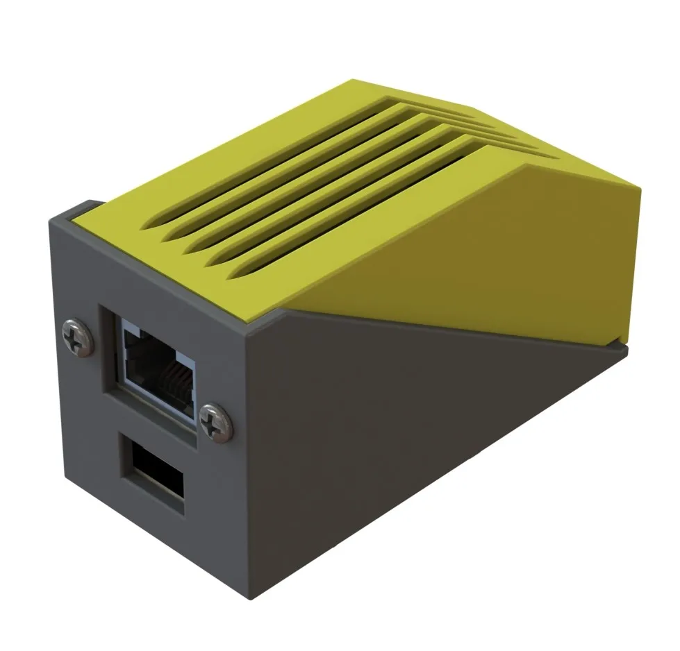
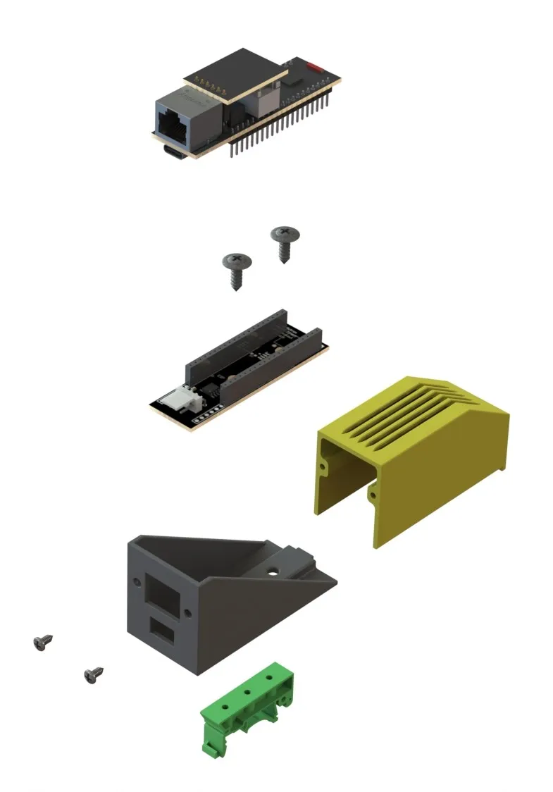
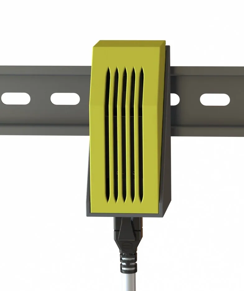
Enclosure
A custom housing was 3D printed to contain the ESP32-S3-ETH and interface PCB as a stacked assembly, with cutouts for the RJ45 port and VE.Direct cable exit. A standard DIN rail clip on the rear face keeps the unit consistent with the other DIN-mounted hardware already in each node enclosure.
Firmware
Firmware is defined in ESPHome YAML. VE.Direct parsing is handled by the community component KinDR007/VictronMPPT-ESPHOME, which implements the VE.Direct text-mode protocol as a set of ESPHome sensor entities. The configuration defines the wired Ethernet interface, UART pin assignment to the ADUM1201 output, the external VictronMPPT component, and Home Assistant API and OTA endpoints. The component exposes all standard VE.Direct fields as Home Assistant sensors automatically — battery voltage, panel voltage, panel power, charge current, load current, charge state, daily yield, and total yield. OTA updates are available over the wired network, meaning firmware can be updated without physical access to the remote enclosures.
Outcomes
Two units have been operational since installation, continuously logging solar charge controller data to Home Assistant. The isolation approach has worked as designed — no ground loop or communication issues observed. The wired Ethernet connection has proven reliable in the outdoor enclosure environment. The per-node cost is a fraction of a Victron Cerbo GX or a Raspberry Pi-based solution, and the maintenance surface is lower: no OS to update, no SD card to fail, OTA firmware updates over the existing network infrastructure.